This document is not intended to be used for terms and definitions of vehicle component terminology. These may appear in SAE J1930.
Circuit/Open—Fixed value or no response from the system where specific high or low detection is not feasible or can be used in conjunction with circuit low and high codes where all three circuit conditions can be detected.
NOTE— The term “malfunction” has, in most cases, been deleted from the DTC description.
Range/Performance—Circuit is in the normal operating range, but not correct for current operating conditions, it may be used to indicate stuck or skewed values indicating poor performance of a circuit, component, or system.
Low Input—Circuit voltage, frequency, or other characteristic measured at the control module input terminal or pin that is below the normal operating range.
High Input—Circuit voltage, frequency, or other characteristic measured at the control module input terminal or pin that is above the normal operating range.
Bank—Specific group of cylinders sharing a common control sensor, bank 1 always contains cylinder number 1, bank 2 is the opposite bank
NOTE— If there is only one bank, use bank #1 DTCs and the word bank may be omitted. With a single “bank” system using multiple sensors, use bank #1.
Sensor Location—Location of a sensor in relation the engine air flow, starting from the fresh air intake through to the vehicle tailpipe or fuel flow from the fuel tank to the engine in order numbering 1,2,3 and so on.
NOTE— See Figures 1 to 4.
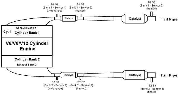
FIGURE 1—V6/V8/V12 CYLINDER ENGINE WITH 2 EXHAUST BANKS AND 4 CATALYSTS EXAMPLE

FIGURE 2—V6/V8/V12 CYLINDER ENGINE WITH 2 EXHAUST BANKS AND 3 CATALYSTS EXAMPLE
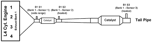
FIGURE 3—L4/L5/L6 CYLINDER ENGINE WITH 1 EXHAUST BANK AND 2 CATALYSTS EXAMPLE
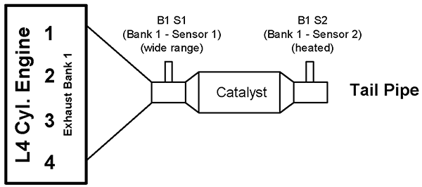
FIGURE 4—L4/L5/L6 CYLINDER ENGINE WITH 1 EXHAUST BANK AND 1 CATALYST EXAMPLE
Left/Right and Front/Rear—Component identified by its position as if it can be viewed from the drivers seating position.
“A” “B”—Where components are indicated by a letter (i.e., A, B, C, etc.) this would be manufacturer defined, starting with component “A”.
Intermittent/Erratic—The signal is temporarily discontinuous, the duration of the fault is not sufficient to be considered an open or short, or the rate of change is excessive.
General Specifications
The following table specifies systems, code categories, hexadecimal values and particular sections of electrical/electronic systems diagnostic.
The recommended DTCs consist of a three digit numeric code preceded by an alphanumeric designator. The alphanumeric designators are “B0”, “B1”, “B2”, “B3”, “C0”, “C1”, “C2”, “C3”, “P0”, “P1”, “P2”, “P3”, “U0”, “U1”, “U2”, “U3”, corresponding to four sets of body, four sets of chassis, four sets of powertrain and four sets of network trouble codes. The code structure itself is partially open-ended. A portion of the available numeric sequences (portions of “B0”, “C0”, “P0” and “U0”) is reserved for uniform codes assigned by this or future updates.
Most circuit, component, or system diagnostic trouble codes are specified by four basic categories:
— General circuit /open
— Range/Performance problem
— Circuit Low
— Circuit High
Circuit Low is measured with the external circuit, component, or system connected. The signal type (voltage, frequency, etc.) shall be included in the message after Circuit Low or Circuit High.
Circuit High is measured with the external circuit, component, or system connected. The signal type (voltage, frequency, etc.) may be included in the message after Circuit Low or Circuit High.
 Leslie